AppHack-e :: 'Appcopter' toy helicopter hack.
Part I: The control signal
This project was originally posted on a blog I hosted for a time on WordPress, hence the magazine copy written format. The post was published July 6th, 2012.
Motivation
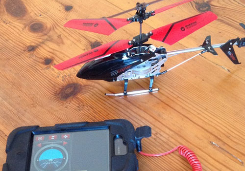
A few weeks ago, I went to a local hobby and model shop to look for inspiration (and maybe something to dismantle). Of particular interest was this: A small infra-red controlled toy helicopter, with a transmitter that plugs into an iPhone - simply download the virtual control panel from the app store to fly it. I was immediately struck by the potential for tinkering; it's rare to see anything 'unofficial' plugged into an iPhone because the platform is so closed (Apple don't let just anyone mess with their hardware), but here was a cheap toy making innovative use of the audio output socket, to fly a vehicle no less - that's pretty clever! As a programmer I could see that in order to make a custom controller for this toy, all that'd be needed would be some code to 'make the right noise down the wire' to the transmitter, so to speak, so with this simple view in mind I went ahead and bought it with some idea of what I wanted to achieve...
Motivation
A few weeks ago, I went to a local hobby and model shop to look for inspiration (and maybe something to dismantle). Of particular interest was this: A small infra-red controlled toy helicopter, with a transmitter that plugs into an iPhone - simply download the virtual control panel from the app store to fly it. I was immediately struck by the potential for tinkering; it's rare to see anything 'unofficial' plugged into an iPhone because the platform is so closed (Apple don't let just anyone mess with their hardware), but here was a cheap toy making innovative use of the audio output socket, to fly a vehicle no less - that's pretty clever! As a programmer I could see that in order to make a custom controller for this toy, all that'd be needed would be some code to 'make the right noise down the wire' to the transmitter, so to speak, so with this simple view in mind I went ahead and bought it with some idea of what I wanted to achieve...
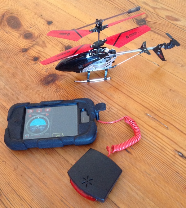
I remember once playing with a programmable robot at school called 'Logo' (nicknamed 'Turtle'), it was a white plastic dome shaped vehicle with wheels, that you could command to perform a series of navigations in sequence, leading the robot to traverse a maze or draw a picture. Program instructions were really simple, you could draw a square by commanding something like the code in the grey box here.
I thought it'd be an interesting challenge to hack this toy helicopter into behaving like a 'flying turtle', so I could send it a series of instructions and watch as it performed them in sequence. That sounds like a pretty simple goal, but to get this far I'd have to achieve a number of tasks, most definitely learning a lot in the process. This modest goal also represents a necessary step on the path to bigger things, such as building a fully autonomous flight platform with sensory feedback systems – now that'd be awesome...
// Go forwards X units and turn right 90 degrees, 4 times.
Forward 10 ;
Right 90 ;
Forward 10 ;
Right 90 ;
Forward 10 ;
Right 90 ;
Forward 10 ;
Right 90 ;
Programming a turtle robot to walk a square
Control mechanics
So after playing with the helicopter for a bit to get a feel for the flight characteristics (cats now run from the room when the toy starts up), I looked at more detail into the available control mechanics.
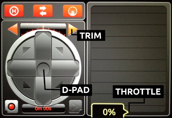
The virtual controller app in d-pad mode
The virtual control panel gives you a number of controls, the most obvious being throttle – how fast the rotors spin, which translates into how quickly the helicopter ascends or descends. Get things balanced just right, and it hovers nicely.
A significant feature of this helicopter is that it has two pairs of 'coaxially mounted' rotor blades – each pair spins in opposite directions, with the effect of mutually canceling any bodily rotation induced during spin. The control circuitry on-board the helicopter manipulates the Y-axis rotation (yaw) of the helicopter in response to your command by slowing down or speeding up just one or the other pair of blades, deliberately allowing a little inductive torque in either direction. There's also 'trim' - it's possible that the unique physiology of the helicopter (factory differences in motor power, for instance) means that some rotational force needs constant compensation; trim allows you to apply some permanent offsetting yaw for this.
Next is pitch, managed by a tiny motor and upwards-facing propeller on the tail boom – spin the rotor one way to dip the tail and make the helicopter fly backwards, or spin it the other to raise the tail and fly the helicopter forwards. Leaving the control untouched allows the helicopter to straighten out and hover.
The app offers two control modes. First is a 'd-pad' ('digital pad') for simple 'zero-or-maximum' forwards, backwards, yaw left, yaw right and combinations of these. Secondly there's a pretty cool mode that allows you to fly the helicopter with the accelerometer of your iPhone by tilting it left, right, forwards or backwards to affect yaw and pitch respectively.
Finally, hidden away in another screen of the app, is a channel selection option: A, B or C - this setting lets you and some friends fly up to three helicopters on different channels, in the same room, each with their own transmitters and controller apps.
Control signal
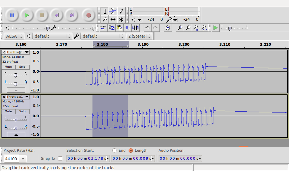
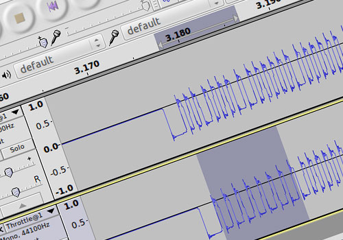
When you fire up the throttle on the app, and the helicopter's motors whirr into action, you can hear the plug-in transmitter box coughing out a staccato series of sounds through a tiny built-in speaker (which on first appraisal could passably be described as 'helicopter rotor noises', made for effect). The same sound is made through the speakers on the iPhone when the transmitter is unplugged, so there must be more to these sounds than mere aural aesthetic; it must be the control signal! It's a pretty straightforward exercise to plug the iPhone's audio output into the audio line-in port on a computer, and record a bit of the sound. It's even easier to then look at it visually portrayed in a sound editing program - here's what the audio signal looks like at two levels of zoom:
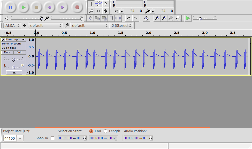
1) A little over 3.5 seconds of audio signal from the app, throttle set at 10%
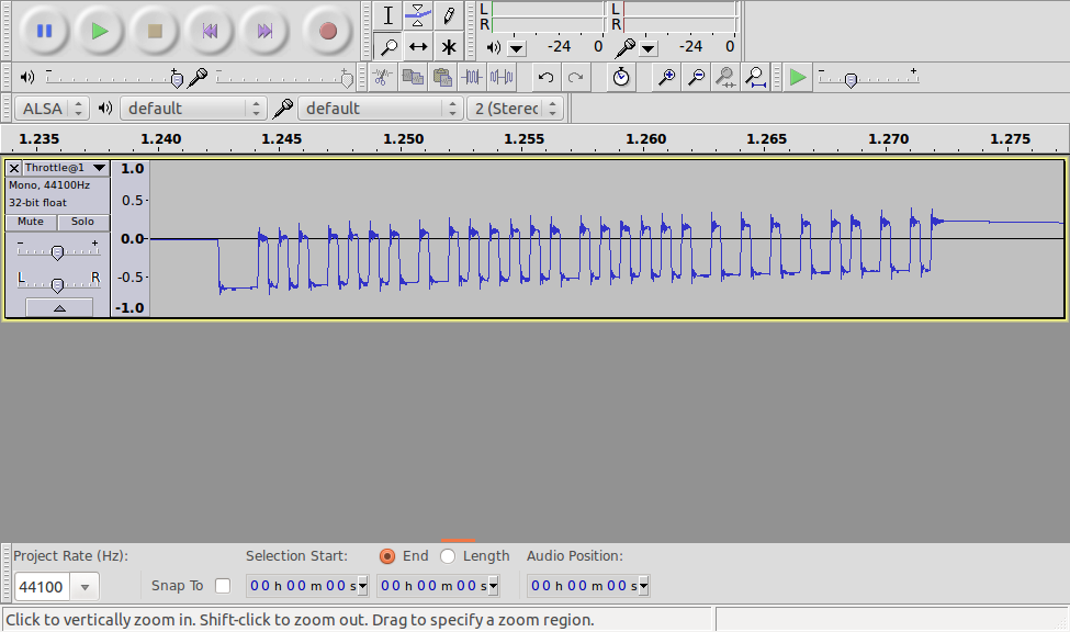
2) Zoomed in upon one of the many individual 'blips' from the signal in image (1). The portion containing dips and peaks is about 30 milliseconds long.
Zoomed right into one of the many pulses visible in image (1), you can see that the signal looks like a series of valleys carved out from a line centered around zero (image 2). Though the signal looks like it tends upwards a bit across its entire length, the 'valley floors' along it look to be of pretty consistent widths and depths, with some looking like exactly double the width of the shorter ones.
This signal above looks most definitely digital (an analogue signal would present a more chaotic and varied looking series of smooth valleys and peaks or different heights and depths, not the regular 'rectangular wave' that we see). A little more research reveals that your average TV remote sends a signal that doesn't look too different to the one sent by the helicopter transmitter... The important point being that the typical TV remote controller signal has a definite structure: it first opens with a 'low signal' or valley of a fixed length (like shouting someone's name to get their attention), the signal data then follows like a spoken sentence, flowing in a series of words: control values spelled out in binary (with the length of the low signal denoting either a '1' or a '0'), before closing with another fixed pattern of lows. Just in case the TV failed to get the message the first time around, the signal is then repeated. It looks like my helicopter similarly has a consistent 'hello' valley at the start (longest trough, far left of image 2), some binary data then follows (with what could be a longer valley denoting a '1', and a shorter valley denoting '0') before coming to a definitive close. The entire signal is repeated again over and over at regular intervals so long as the throttle is greater than zero - setting the throttle to zero stops the signal audio.
A brief moment to explain binary...
When we count from 0 to 9, we visit a series of unique numerical symbols in one 'column', which we call the 'units': 0, 1, 2, 3, 4, 5, 6, 7, 8, 9. When we get to the number 10, we wrap over into two columns: the 'tens' (of which we have one in this instance) in addition to the 'units' (of which we have none). Count up to 100 and we have one 'hundred', no 'tens' and no 'units'. Following so far? We've just been counting in 'base-10' – our numerical system is in fact built around base-10. We don't have to constrain ourselves to 'units', 'tens', 'hundreds', etc. though - you can effectively work in a numerical system of any base - binary is simply counting in 'base-2'! The table below shows exactly what that looks like – on the left is the familiar number in base-10, on the right is the same number, in binary. See that instead of 'tens', 'hundreds' and 'thousands' (powers of ten), we instead have 'twos', 'fours', 'eights', 'sixteens', etc. (powers of two), with each column being shifted along to the left when the smallest gets filled.
When using binary in computing, it's typical to specify a number with a certain length of symbols - like putting in a placeholder '0' for each column we might possibly use - this is the number of 'bits' ('binary digits') used to specify the number:
The number 1 in 'four bit binary': 0001
The number 15 in 'four bit binary': 1111
So what happens if we try to specify the number 16 in four bits? We just can't do it! There's a limit to the maximum number we can specify with a certain number of bits. To show the number 16 in binary we need at least five bits:
The number 16 in 'five bit binary': 10000
Numbers 1 to 10, in a nutshell:
'Columns' in binary read from right to left: 1, 2, 4, 8, 16, 32, 64, 128, 256...
1 (one 'unit') → 1 (one 'one')
2 (two 'units') → 10 (zero 'ones' plus one 'two')
3 (three 'units') → 11 (one 'one' plus one 'two')
4 (four 'units') → 100 (one 'four' plus no 'two' and no 'one')
5 (five 'units') → 101 (one 'four' plus no 'two' and one 'one')
6 (six 'units') → 110 (one 'four' plus one 'two' and no 'one')
7 (seven 'units') → 111 (one 'four' plus one 'two' and one 'one')
8 (eight 'units') → 1000 (one 'eight' plus no 'fours' plus no 'two' and no 'one')
9 (nine 'units') → 1001 (one 'eight' plus no 'fours' plus no 'two' and one 'one')
10 (one 'ten', no 'units') → 1010 (one 'eight' plus no 'fours' plus one 'two' and no 'one')
Decoding the binary signal
So we've seen what controls the helicopter responds to: throttle, yaw, pitch, trim, and channel. The signal data must contain information about each of these - there's no magic happening when you push up the throttle control! We've established that the signal is binary in format; it's sending a series of numbers represented by zeroes and ones - these numbers must mean something about each control, but in what order do the values get sent, and by how many bits is each represented? With applied scientific method, we can easily figure out the signal encoding! The process is really simple:
- Choose just one variable (be it throttle, yaw, pitch, trim or channel) and modify it to a known value, for example, set throttle at 10%. Record the signal audio - this is our 'control' signal, against which all further modifications will be compared.
- Change the selected variable by a small amount, for example, set throttle to 20%. Record the signal audio.
Signal comparison: Throttle at 10% (top) and 100% (bottom). There's definitely something going on with those first few bits of signal (highlit, bottom)
- Open up the audio file for the control signal (in this case throttle at 10%), and place alongside it the audio for the latest recording (throttle at 20%) - see how the signal changes between the two wave forms (image 3) - there's clearly a connection between a particular variable (throttle in this case) and the part of the second recording that changes in response.
- Repeat many times, for a range of control settings for a particular variable, before moving onto a different variable and starting over!
I found it possible to get a pretty big hint about the location of a particular control value on the signal, with a little trick: the controls have maximum and minimum values (for example, throttle has both a 0% and 100% setting), so assuming these aren't mapped to weird arbitrary values, they must be equivalent to the value on the signal - the signal should show the highest value for throttle, say, when the app has it set at 100%. So set the throttle to 100%, and the signal shows a series of long valleys (obviously then our 'ones') at a location that must contain the throttle value!
I initially started writing a program to automate the full testing procedure, exporting the audio files to a text file format (thinking it may be quicker to crunch the numbers that way). I eventually ran out of patience with this though after encountering a number of issues, and resorted to pencil and paper - it turned out to be pretty swift afterall - about an hour to figure out the encoding, and like any puzzle, really good fun.
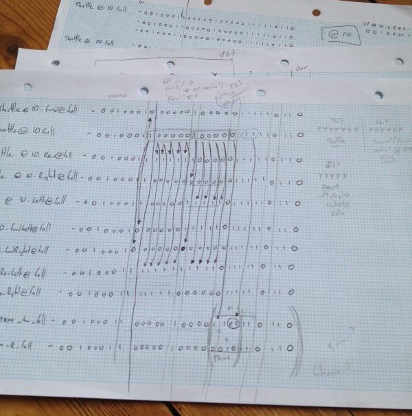
Pencil and paper: Change one aspect of the control (e.g. set throttle @ 20%) and see how the signal changes relative to some base setting (I used throttle @ 10% as my reference signal). Repeat many times, identifying the characteristics of the control components of the signal
The signal exposed
There's a lot of content in this post, so I'll deliver the story in two parts. In the next post I'll reveal the program written in Processing to generate the audio signal for the transmitter, and talk about automating the helicopter's flight! For now, here's a summary of my findings, and everything you need to start writing a program to take control of the helicopter:
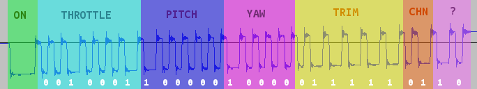
- The audio signal is a rectangular waveform representing binary data, with a normalised peak amplitude 'pulse' of about 0.6 units, when represented in uncompressed .wav file format.
- The signal begins with an 'on' pulse of ~1600 microseconds
- A binary '0' is indicated by a pulse of ~400 microseconds following a gap of ~400 microseconds
- A binary '1' is indicated by a pulse of ~800 microseconds following a gap of ~400 microseconds
- The entire signal carries 28 bits
- Following the on pulse the controls are sent as follows:
Throttle: 7-bits, defaulting to 0, full at 127
Pitch: 6-bits, defaulting to 32, full forwards at 0, full reverse at 63
Yaw: 5-bits, defaulting to 16, full right at 0, full left at 31
Trim: 6-bits, defaulting to 31, full right at 0, full left at 63
Channel: 2-bits, A: 1, B: 2, C: 0
???: 2-bits, no idea - let's find out in part two of this two-part series!
More projects
SpidertownDigital Art

Toon Cup 2022 updatesHTML5 Game
Dodger: WantedHTML5 Game

The HuntsmanDigital Art

The Little MermaidDigital Art

Snow WhiteDigital Art

RapunzelDigital Art

Red Riding HoodDigital Art
Global Game Jam 2020: REPAIRHTML5 Game


LabuntinaIn-app HTML5 Game

Tee and Mo: Little WorldHTML5 Game
Word TrainHTML5 Game

Flip and MatchHTML5 Game


Hydra3D Art

Blue Bird3D Art

RainbowSpill3D Art

Vanity3D Art

Gumball Guy3D Art
Helmet Guy3D Art

Wired Eyed3D Art

Cauldron Guy3D Art

Jelly Crab3D Art

Kraft3DHobby business
Papercraft fishMake

Paperfishion3D Art

BAFTA KidsVideo Appearance

The Next StepGame Character

GyaradosGame Character

Gastly3D Render

Iron Man Poster3D Render
Art Station ChallengeGame Character
Construction Site Lamp3D Render

LileepGame Character

Stareoke StagefrightFlash Game
Richard Hammond's Blast LabFlash Game

Blue Peter: Turkish BizarreFlash Game

The Right MixFlash Game
Big and SmallFlash Game

Tate AirbrushFlash Game

Tee and Mo Face PaintingHTML5 Game

Tee and Mo WebsiteWordpress Website
Zingzillas: The Great Coconut AdventureFlash Game

Tree Fu TomFlash Games
Let's PlayUnity3D/Flash Game
Elmo Loves 123sAIR App: iOS and Android
All Star RacingHTML5 Game
Crabtree PlusWordpress Website, HTML5 games

TwirlywoosHTML5 Games
The OctonautsHTML5 Website, Flash games

Elmo's Art MakerHTML5 Game

Pop and SpellHTML5 Game

Paw Patrol Air PatrollerHTML5 / HAXE Game
Tee and Mo Playtime (iOS, Android)AIR App: iOS and Android

Operation Ouch: Snot ApocalypseHTML5 Game

MegamanGame Character
Operation Ouch: Clone WardsHTML5 Game

SupernormalsDigital Art

The Lion KingDigital Art
Alan Owen:
Creative Developer (geographically based near Worthing, UK).
INDUCTIBLE LTD
Registered in England and Wales with company number 13501602
Registered office: 3rd Floor 86-90 Paul Street, London, EC2A 4NE
Developing rich interactive content since 2004
